Circuits
Resistors, Capacitors, Inductors, Oh my!
Source
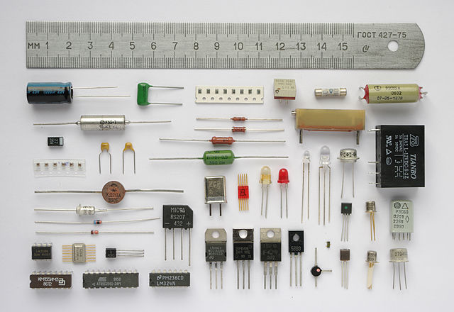
We’ve studied circuits before6: that large conglomeration of protruding wires, resistors, capacitors, inductors, and some type of potential difference all jumbled up together that somehow make things happen. Let’s learn some more, shall we? New kinds of circuits await our exploration.
LC Circuits
As its name implies, an LC circuit has both an inductor (L) and a capacitor (C). As opposed to the other types of circuits we’ve looked at, this combination creates an oscillating charge and current. How does it work?Let’s briefly review the parts of the circuit: a capacitor stores charge across two metal plates, just like we studied with Gauss’ Law. The electric field of a capacitor can be described as
 , though we’re not so interested in the electric field at the moment as we are interested in the charge and how it affects the LC circuit.
An inductor resists changes in current because it’s a coil of wire. Sound familiar? A cylindrical inductor is called a solinoid, and since they are so common, we sometimes use the words interchangeably. We calculate inductance by
 , where I is the current, N is the number of turns, and Φ is flux, so for a solenoid with Φ = μ0nIA, then the inductance becomes L = μ0nNA, where A is the area, n is the turns per length, and N is the total number of turns. Inductance L has units of Henrys, H.
 *Pause*
A lot of scientists who dabbled in electricity and magnetism in the 1800’s have something named after them, like all the laws we’ve talked about and units of measurement of Amperes, Ohms, Henrys, Coulombs, Volts, Teslas, you name it. It pays off to discover things.
*Now, back to our regularly scheduled programming*
Here are some diagrams of LC circuits.


Above we see an LC circuit with an open switch. When the switch is open, the capacitor has a potential difference of Vm and an initial maximum charge of Qm= CVm with electric energy
 . What happens if we close the switch?
The capacitor begins to discharge as current begins to flow. As the capacitor discharges, its potential equals the electromotive force ε induced in the inductor. This means the change in current slows down, until a maximum value Im is reached. When this happens, then both the potential V and the EMF ε are zero. The energy initially stored in the capacitor’s electric field is now fully transferred to the inductor coil’s magnetic field as magnetic energy,
 . Since inductors resist current changes, current continues to flow with this magnetic energy. The magnetic field then begins to decrease.
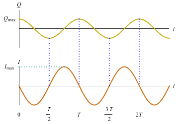
Then, sure enough, the same thing happens but in reverse. The capacitor charges with a polarity opposite to what it was formerly as the current slowly increases, now flowing in the other direction. Eventually, it reaches maximum charge again…and we are back at square one. The charge and current permanently remain 90˚ out of phase. Every time the inductor releases a current, it produces a magnetic field, and every time the capacitor stores charge, it produces an electric field. Back and forth, like ping-pong.
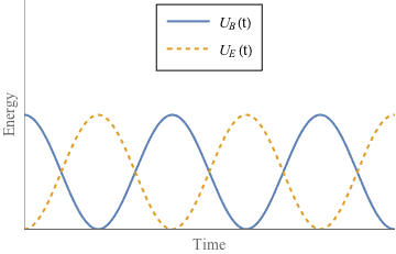
As we said, this is an oscillating circuit: charge flows through the inductor as current and builds up between the plates of the capacitor and repeats, while energy U oscillates between the capacitor and the inductor at the frequency
 . With nothing to stop their game of hot-potato, an ideal LC circuit oscillates forever.
RLC Circuits
Ideal doesn’t happen in the real world, so we’re going to investigate the effects of the internal resistance that will ultimately destroy our perfect harmonious oscillating LC magic.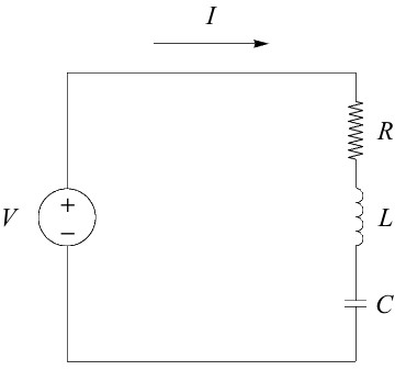
As the current flows back and forth, a tiny bit of energy is lost as heat. Wires all have some internal resistance, even if it’s low compared to the resistance of an official resistor. To analyze the effects, though, we add a resistor with resistance R into an LC circuit and poof! We now have an official dyed-in-the-wool RLC circuit. If R is relatively small, then we have damped harmonic motion, creating what looks like a dying wave. It looks that way, because that’s exactly what it is. See?
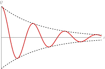
The size of the resistance affects the oscillations of current and energy within the circuit. A small resistance leads to underdamped oscillations. This means the circuit still oscillates, but gradually loses energy as heat as shown in the diagram above. If we increase R, it’ll come to a point where the circuit won’t oscillate any longer. Boooo. We call this point a critically damped circuit
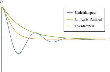
The bigger the R, the faster the oscillations die, or the faster charge approaches zero. And what happens if we make R even bigger than for critical damping? We get an overdamped circuit. These cases are drawn below for us to scrutinize and permanently etch in our memory:
In a nutshell, the difference between an RLC circuit and an LC circuit is the LC circuit happily bounces the energy ball back and forth between electricity and magnetism, but the resistor in an RLC circuit steals the energy from the ball so it can’t rebound.
The natural frequency of an RLC circuit is the same as for an LC circuit, because it’s the inductor and capacitor which determine the rate of exchange of energy and charge. Again, that resonant frequency is
. We only see this natural frequency for greately underdamped RLC circuits, though. As shown in the diagram above, oscillations depend on whether the circuit is over- or underdamped.The frequency at which a damped circuit oscillates is
 . If
. If  , then it oscillates. If
  , then the circuit is overdamped. If they’re equal to each other, then the circuit is critically damped.
 Let’s practice. An RLC circuit has a resistance of 900 Ω, a capacitor of 250 nF, and an inductor of 300 μH. What is the resonant frequency of this circuit and how may we describe the damping in this circuit?
First of all,
 and
and  . The resonant frequency is always
  . Next we compare
  and
and  which is
  . The piece with resistance is larger than the piece with LC, leading to an overdamped circuit.